• This equipment is only to be used by qualified professionals.
ATTENTION! Avoid use of the LED Piezoelectric scaler around pacemakers.
- It has been shown that electronic appliances including medical devices may interfere with normal operations of pacemakers. It is suggested that patients or professionals who have pacemakers avoid using a LED Piezoelectric scaler.
• The Inovadent™ HS4W LED Dental Cart should be powered from a separate wall outlet with a grounding point.
• Do not dismantle the machine. Violation of this requirement may cause harm to the user or machine and void the Warranty. Please call Inovadent at +44 1225 791 184 (Europe); 1.800.523.8185 (United States) before removing any protective covers.
• If any abnormal situations are observed while the machine is in use, unplug the machine and call technical support at +44 1225 791 184 (Europe); 1.800.523.8185 (United States).
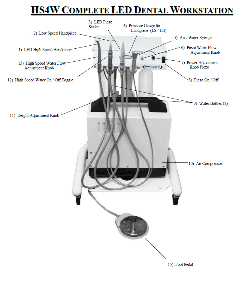
Unit Diagram
Unpacking & Set-Up
1. Unpack carefully from crate. Tools required: flat head screwdriver and paper towel. (Packaging should be kept for future shipping purposes; in the event the entire unit needs to be returned for service).
2. Remove Operation Guides (Dental Cart & Compressor), handpieces, and water bottles.
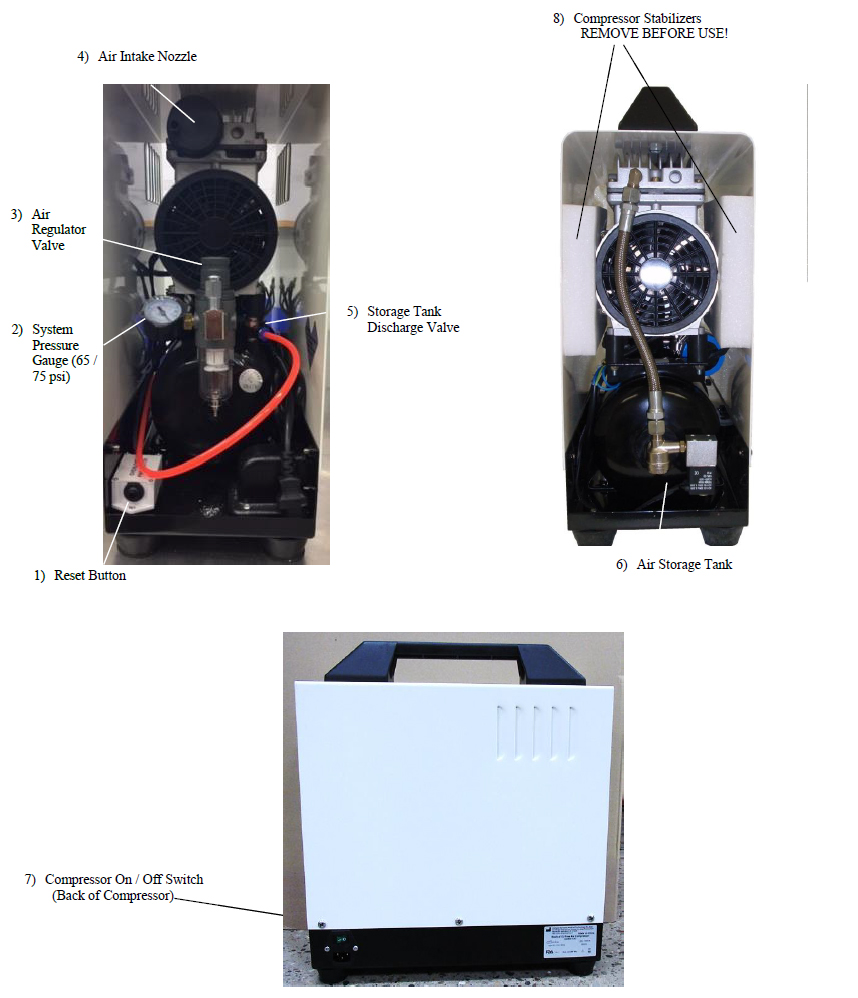
3. Remove Foam Compressor Stabilizers from DynAir® Compressor. See Page 6 (Item 8)
4. Adjust height by turning the cart height adjustment knob on center pole. Support cabinet while adjusting knob. See diagram on Page 4 (Item 11).
5. Fill water bottles with distilled water and Ultra Scale™ and attach under left side of cabinet. See diagram on Page 4 (Item 9).
6. Follow manufacturer’s instructions on pages 18 and 19 to carefully attach High Speed and Low Speed Handpieces.
7. Attach a KLAW™ tip to the LED Piezoelectric scaler handpiece, tighten with KLAW™ wrench until snug.
Warning: Do not over tighten KLAW™ as it may damage the LED Piezoelectric Handpiece.
Note: LED Piezoelectric scaler instructions are located on pages 8-10; please read instructions before attempting to operating unit.
8. Plug power strip located on the back of the compressor into a (110V United States) (220V Europe) outlet grounded outlet.
9. Ensure the following are plugged into the power strip: 24 VAC Transformer (if available) and compressor.
10. Turn on power strip to supply power to cart.
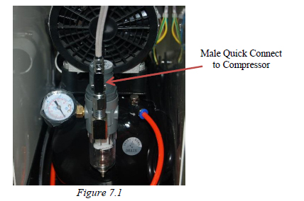
11. Connect male quick connect to compressor (See Figure 7.1). This will provide pressure to LED High Speed, Low Speed and LED Piezoelectric Handpieces and Air & Water systems.
12. Gauges are visible to monitor pressures. The following pressures provide optimum efficiency and safety of the unit. Simply remove a handpiece and depress foot pedal to verify pressure.
Filter Housing / System Pressure: 65 - 75 psi (Warning: Do not adjust pressure above 75 psi).
LED High Speed Handpiece: 35 - 40 psi
Low Speed Handpiece: 25 psi
Water Pressure: 25 - 30 psi
LED Piezoelectric Handpiece: 58 - 60 psi
13. Operating pressures for each handpiece have been factory set; however, minor adjustments may be required due to shipping - see “Adjustments” below.
Adujstments After Shipping
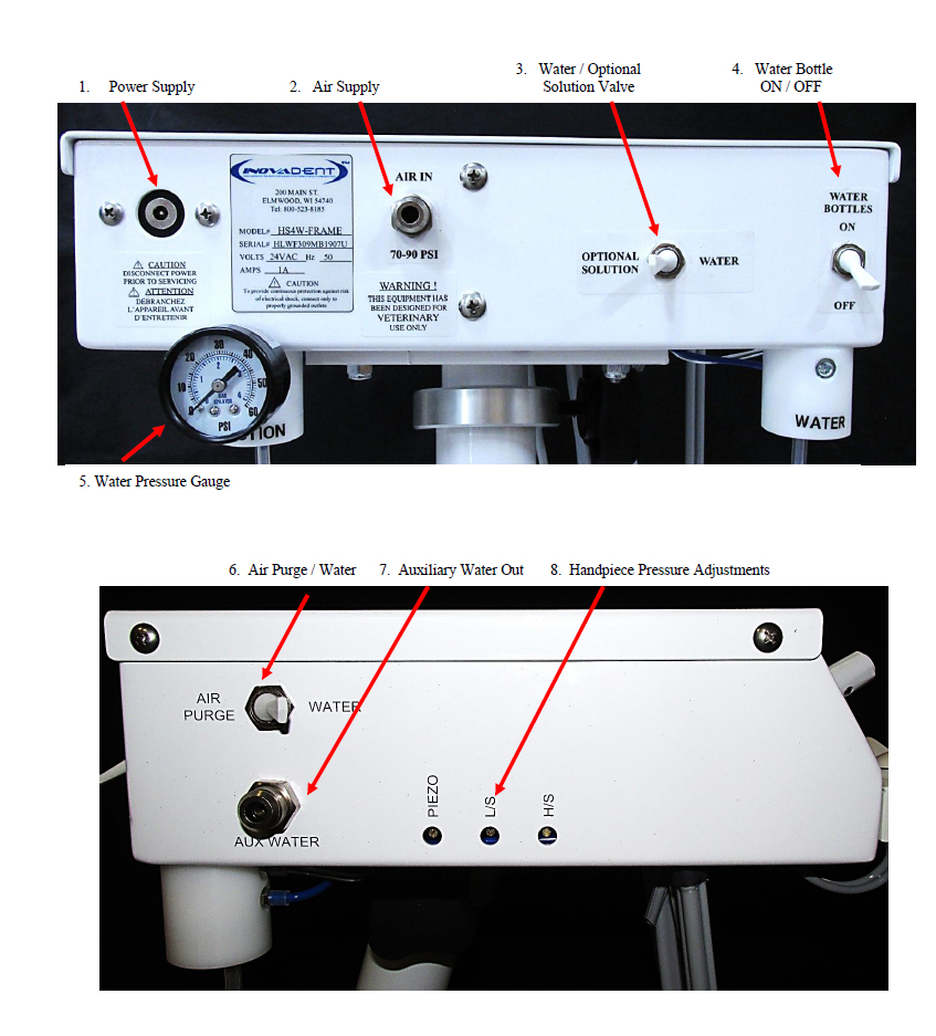
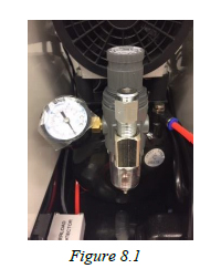
A. Verify the air pressure discharge from the air regulator / filter (gauge located between the air tank and the compressor motor on the front of the unit) is at 65 - 70 psi (See Figure 8.1).
B. If adjustment is needed, pull up on the air regulator valve to unlock the adjustment knob, then turn the knob clockwise to increase the pressure and counterclockwise
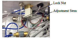
C. Verify the water system air pressure is reading from 25 - 30 psi, See diagram on Page 5 (Item 5). The pressure regulator is located inside of the cart storage top. Loosen the lock nut, then turn the adjustment stem clockwise to increase pressure and counterclockwise to decrease the pressure. Once the proper pressure has been set, retighten the lock nut.
Note: The pressure regulator is not self-bleeding and pressure will have to be relieved by turning the water bottles off and on.
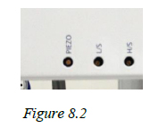
D. Handpiece operating pressure adjustments are made by turning the three adjustment screws located on the left side of the cabinet located on left front side of the unit (See Figure 8.2). Adjust operating pressures as follows:
➢ High speed operating air pressure is 35 - 40 psi. To verify pressure, remove handpiece, depress foot pedal and observe pressure gauge on front panel above handpiece rack. If adjustment is needed, turn the far right adjustment screw clockwise to decrease, or counterclockwise to increase, pressure while depressing the foot pedal. The adjustment knob is very sensitive, so a minor adjustment will cause a significant change.
➢ Follow the same procedure as above to adjust the Low Speed Handpiece (the middle adjustment knob) to 25 psi.
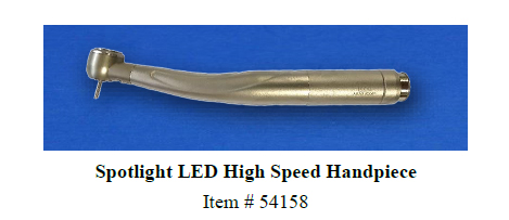
LED High Speed & Low Speed Handpieces
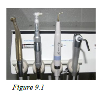
The handpieces have pre-designated holder positions as follows: High Speed or High LED High Speed far left, Low Speed second from left, LED Piezoelectric Scaler second from right and Air / Water Syringe far right (See Figure 9.1).
Note: Handpiece holder positions have been temporarily labeled. The labels can be removed at any time.
Individual handpieces are ready for use when selected and lifted from the holder. Handpieces other than the Air / Water Syringe, must be returned to their pre-designated holder positions before picking up another handpiece for use.
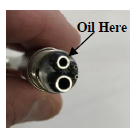
Oil LED High Speed and Low Speed Handpieces prior to first use, and oil before and after daily use. Oil is placed into the smaller of the 2 large holes at base of the handpiece (See Figure 9.2). Use of spray cleaner and lubricant such as Bio Lube™ is recommended. If using simple oil as a lubricant, place four drops into appropriate hole, reattach handpiece and flush through with air for 20 seconds. Failure to oil after each use will void the warranty.
Note: Handpieces should be cleaned with Bio Lube™ cleaner weekly.
Once a week remove the bur blank and place two drops of oil into the turbine.
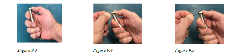
Always leave a bur or rod insert in the LED High Speed Handpiece when not in use. Failure to do so voids the warranty. Burs are changed by a push button on the handpiece
(See Figures 9.3, 9.4 and 9.5).
The LED High Speed Handpiece can be used with or without water. If water is desired, turn the far left toggle switch to ON, see diagram on Page 4 (Item 12). To increase water flow, turn the adjustment knob to the left, or counter-clockwise; to decrease water flow turn to the right, or clockwise. See diagram on Page 4 (Item 13).
The Low Speed Handpiece is not fitted with a water supply. Depressing the foot pedal activates drive air for the handpiece motor. This handpiece is used for polishing.
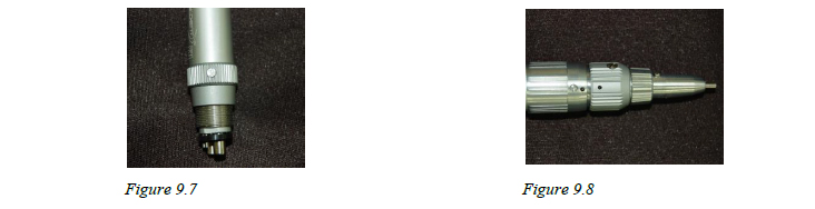
Note: The Low Speed Handpiece must be aligned as pictured for proper operation (See Figures 9.7 and 9.8)
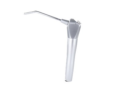
Air/Water Syringe
To operate the Air / Water Syringe, lift the syringe from the holder and depress the respective button(s) on handpiece to obtain either air or water, or both.
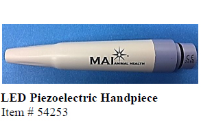
Built-in LED Piezoelectric Scaler and Handpiece
To connect the LED Piezoelectric Handpiece to the cord, align the four pins and water supply port on the handpiece with the cord. Insert the handpiece into the cord coupler, and gently, but firmly, push the handpiece into the cord coupler. Do not twist, turn or unscrew the handpiece while inserting into or removing from the cord coupler. This will break the connectors in the handpiece and cannot be repaired and will void the warranty.
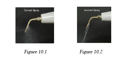
To operate the LED Piezoelectric scaler, press the LED Piezoelectric Power switch to ON, see diagram on Page 4 (Item 8). Lift the LED Piezoelectric Handpiece from the holder, set the power adjust and water flow and press on the foot pedal. Water should be adjusted to a fine mist (See Figures 10.1 and 10.2).
The built-in LED Piezoelectric scaling system power settings can be used in a range from 1 through 10 (1 being the lowest setting and 10 being the highest). The procedure will determine the tip selected and power level used. Refer to the table located on Page 11, “Power Settings & Use of KLAW™ Tips”, for recommended power settings.
Note: If power range exceeds recommended settings below, this may cause tip breakage.
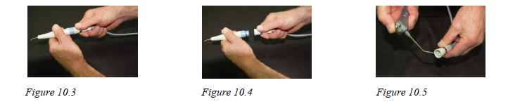
To disconnect the handpiece from the cord, hold the handpiece by the purple ring in one hand and the cord coupler in the other hand, then pull apart (See Figures 10.3 and 10.4). Do not pull on the cord! Doing so will void the warranty. After disconnecting the handpiece, it is recommended to use the Air / Water Syringe to blow any left over water from the connector (See Figure 10.5). Water or fluid left in the cord coupler may render the unit inoperative for future use.
Disconnect the Handpiece
Piezo Care & Maintenance
Disconnect the LED Piezoelectric Handpiece from the cord and clean the handpiece with a disinfectant (non-chloride, non-iodine). Do not spray the handpiece with disinfectant while attached to the cord. Do not immerse in any solution, including ultrasonic or cold sterile solutions, as this will damage the handpiece and void the warranty. Dry handpiece with a clean cloth or gauze square. Place handpiece in a sterilization bag or autoclavable box and autoclave for 3 minutes at a maximum of 275° F / 135° C. (Ensure KLAW™ tip has been removed from the handpiece prior to autoclaving. Failure to separate the tip from the handpiece will cause the tip to fuse to the handpiece). Additional handpieces may be purchased to accommodate autoclave turnaround time.
Note: The use of a rapid heat sterilizer is not recommended.
Remove KLAW™ tip prior to autoclaving
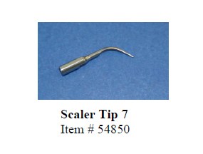
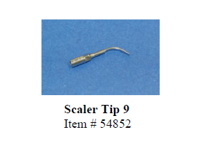
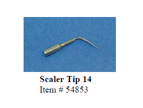
KLAW™ Veterinary Ultrasonic Tips
KLAW™ Tip Installation
KLAW™ Tip Technique
Power Settings & Use of KLAW™ Tips
KLAW™ Tip Care & Maintenance
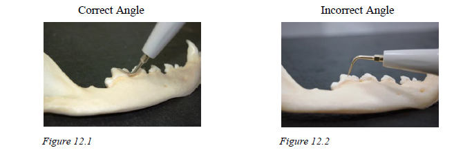
KLAW™ Tip Angles
KLAW™ Tip Installation
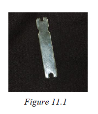
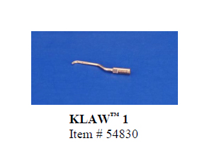
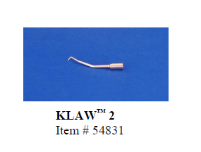
The HS4W LED Dental Cart includes three KLAW™ tips; KLAW™ 1, KLAW™ 4 and KLAW™ 6. To install a tip on the handpiece; hold the handpiece in one hand, place the KLAW™ tip on the end of the threaded shaft and then rotate the tip to the right until it is finger tight. The tip wrench must be used to tighten the KLAW™ until snug to assure proper operation of the scaler (See Figure 11.1).
Note:Do not over tighten KLAW™ tip; this may cause breakage of the handpiece stud.
KLAW™ Tip Technique
It is very important to use a feather light touch with the tips. Too much pressure can cause damage to the KLAW™ as well as the patient’s teeth. The KLAW™ tip and the LED Piezoelectric scaler will do the work; it is not necessary to apply pressure or push down. You will get optimal results by simply using a light paint brush stroke with the side of the tip, gently guiding the handpiece and tip, using the same pressure as if writing with a pencil or similar to periodontal probing.
Power Settings & Use of KLAW™ Tips:
Tip #
Power Setting
Use
1
4 - 6
Universal small scaler designed for root surfaces and sub-gingival curettage. Note: If used on cats or small dogs start with power setting of 2 and adjust as needed.
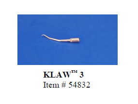
2
2 - 3
Delicate finishing tip excellent for cats and small dogs. Left 30° angle for difficult to reach surfaces. Recommended for R mandibular buccal surfaces, L mandibular lingual surfaces, L maxillary buccal surfaces and R maxillary lingual surfaces. Not for heavy calculus. Use a very light touch. Note: If used on cats or small dogs start with power setting of 2 and adjust as needed.
3
2 - 3
Delicate finishing tip excellent for cats and small dogs. Version of #2. Right 30° angle tip for difficult to reach surfaces. Recommended for L mandibular buccal surfaces, L maxillary lingual surfaces, R mandibular lingual surfaces and R maxillary buccal surfaces. Use a very light touch. Note: If used on cats or small dogs start with power setting of 2 and adjust as needed.
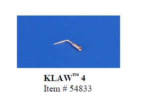
4
4 - 6
Universal tapered tip, with a 110° angle. Ideal for all surfaces, especially inter-dental spaces and root scaling. The #4 tip can also be used for flushing pockets. Note: If used on cats or small dogs start with power setting of 2 and adjust as needed.
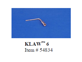
6
6 - 8
Longer shaft version of #4, with a wider diameter and knurled tip for more aggressive removal of heavy calculus. Note: If used on cats or small dogs start with power setting of 2 and adjust as needed.
KLAW™ 1, KLAW™ 4 and KLAW™ 6 are the most commonly used.
KLAW™ tips will need to be replaced, on average, every 3 - 4 months, based on appropriate use and 8-10 dental procedures per week.
Warning:Turn power to LED Piezoelectric Scaler off when changing KLAW™. If the foot pedal is accidentally depressed while the power is on and attaching a tip, the tip could break.
Turn power to LED Piezoelectric Scaler off when changing KLAW™
KLAW™ Tip Care & Maintenance
KLAW™ tips should be cleaned after each use. If placed in an ultrasonic or cold sterilization solution, tips should be rinsed and dried prior to sterilization. Care should be taken to prevent the tips from touching one another while autoclaved. Heat from the autoclave cycle can deform or break tips if they touch one another. Autoclave the tips at a maximum of 275° F / 135° C for 20 minutes in a protective package or 3 minutes without packaging.
KLAW™ Tip Angles
Tips should lay flat to the tooth when cleaning (See Figure 12.1). The points should not be used to scale teeth (See Figure 12.2).
Note: Do not use KLAW™ tips as picks. This will cause breakage and void the warranty.
End of Day Procedure
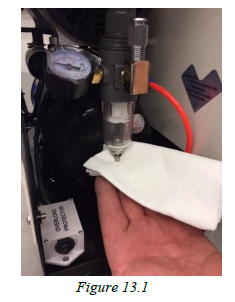
1. Place a paper towel below the base of the air filter cartridge canister and then depress the small button on the bottom of the cartridge to purge moisture from air system (See Figure 13.1). Inovadent recommends changing filters annually.
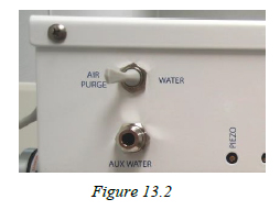
2. Purge all water from handpiece cords. Water must be purged from the LED High Speed Handpiece, the Air / Water Syringe, and LED Piezoelectric Handpiece daily. Switch the WATER ON to AIR PURGE (See Figure 13.2).
- Remove the LED High Speed Handpiece from the holder. Hold the handpiece over a sink or a bucket and depress the foot pedal until water no longer sprays from the handpiece.
- Remove Air / Water Syringe from the holder. Hold the syringe over a sink or a bucket and depress the water button until water no longer sprays from the tip.
- Remove LED Piezoelectric Scaler from the holder. Depress foot pedal until water no longer sprays from the KLAW™ tip.
3. Remove LED High and Low Speed Handpieces.
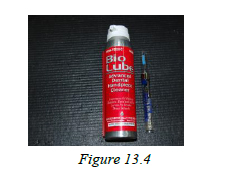
4. Holding handpiece in a paper towel, flush airline and exhaust line with Bio Lube™ cleaner. Place four drops of oil into the drive airline (See Figure 13.3). Reattach, then depress the foot pedal and blow air through the handpiece for 15 to 20 seconds.
Note:LED High and Low Speed Handpieces should be cleaned weekly and oiled daily.
a. Inovadent recommends using Bio Lube™ for the cleaning and lubricating process (See Figure 13.4).
5. Turn the water bottles toggle switch to the OFF position (See Figure 14.1).
6. Wipe down cart, cords and handpieces with water and non-chloride non-iodine disinfectant.
7. Remove KLAW™ tip from LED Piezoelectric Handpiece, carefully clean and place in storage box.
8. Remove bur from LED High Speed Handpiece and replace with blank bur.
9. Unplug cart from wall outlet if storing cart in another location or turn off power strip.
10. Store handpieces in original storage containers (LED High, Low and LED Piezoelectric).
11. Replace all handpiece cords to rack to keep cords clean and from being stepped on.
12. Place the end of the tank drainage hose into small bottle and press the drain valve using slight pressure to expel moisture from the tank. See page 6 (Item 5).
DynAir® Compressor
Review the Operation Manual before use.
The DynAir® compressor is covered by a one year manufacturer’s warranty.
Technical Support
Please contact Inovadent with any technical support questions.
Inovadent™- Europe
Unit 4 Merlin Way | Bowerhill Industrial Estate | Melksham | Wiltshire | SN12 6TJ
Inovadent™ warranties pneumatic components against defects in materials for a period of 3 years unless otherwise specified. Electronic components are subject to a 1 year warranty. Labor is not covered under warranty.
- DynAir® Air Compressor is covered by a manufacturer’s 1 year parts warranty. The air tank is also covered by a manufacturer’s 1 year warranty.
- LED High Speed Handpiece is covered by a 1 year warranty.
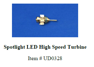
- High Speed turbine is covered by a 6 month warranty.
- Low Speed Handpiece is covered by a 1 year warranty.
- LED Piezoelectric Handpiece is covered by a 1 year warranty.
- Warranty does not cover any product that has been subject to improper use, neglect, accident or use that is in violation of the instructions described in the instruction manual. Merchandise returned as defective will not be replaced until it has been determined to be defective by Inovadent™. Please allow up to 4 weeks for this process. Products that have been repaired by someone other than an Inovadent™ technician or products that have been taken apart by the customer are no longer covered under this warranty unless so instructed by an Inovadent™ technician.
- The customer is responsible for shipping warranty items to Inovadent™ for evaluation. Any items found to be faulty will be replaced by Inovadent™, including return shipping to the customer.
- Warranty is conditional on proper use and maintenance of the unit.
- Warranty is limited to repair or replacement at manufacturer’s discretion.
- Under no circumstances will the manufacturer be held responsible for incremental or consequential damages.
- For all warranty inquires, call Inovadent™ directly at +44 1225 791 184 (Europe); 1.800.523.8185 (United States).
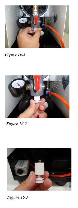
Changing Air Filters
1. Remove the black sediment bowl from the air pressure regulator by turning the bowl clockwise (See Figure 16.1).
2. Remove the filter from the regulator by turning the filter clockwise.
Replace the old filter by turning the new filter counterclockwise.
Reattach the separator bowl by turning the bowl clockwise until snug(See Figure 16.2).
3. Slide filter out of its cradle and replace with a new filter (See Figure 16.3).
Make sure spring is attached to the cradle when reattaching the cradle to the regulator.
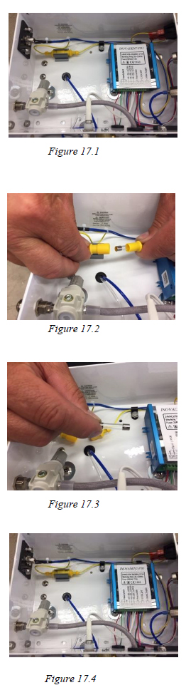
Checking & Changing Fuses
1. Turn power off for the entire unit by unplugging the dental unit from the wall outlet. Ensure all power has been disconnected. Remove the lid by removing the four screws.
2. Locate the yellow fuse holder. Separate the fuse holder. (See Figure 17.2).
Note:Do not pull on the wires, it may damage the connection.
3. Check the fuse for continuity. If the fuse needs to be changed, remove the spare fuse from its holder. Fuses may be purchased from an Inovadent™ distributor or local electronics store (See Figure 17.3).
4. Once the fuse has been replaced, reconnect the fuse receptacle.
Then plug the power cord into the dental cart and into the wall outlet before testing (See Figure 17.4).
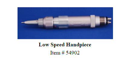
High Speed Handpiece
Low Speed Handpiece
This product is designed for veterinary dental use. Operation and maintenance should be performed under the supervision of a veterinary dental professional.
1. Bur Change: The bur-locking position occurs when the black dot on the locking ring is adjusted to a position in which it is located directly above the black dot on the position ring. To open the chuck for a bur change, twist the locking ring until the black dot is located above the red dot.
MAINTENANCE: To keep the Low Speed Handpiece in good condition, only use dental handpiece oil. Inovadent™ recommends using Bio Lube™. Lubrication should be performed daily after cleaning the unit.
1. Lubrication
Be sure to lubricate after autoclaving or in the event that water and / or dust gets inside. Place 4 drops of lubricant oil in the drive-air (the smaller of the two holes) at the back of the Low Speed Handpiece. Reattach the handpiece to the unit and run the handpiece for 8 to 10 seconds.
* Hold handpiece firmly. Dropping the handpiece may cause damage.
2. Surface Cleaning
Clean with brush and wipe off by cloth. Lubricate after surface cleaning. DO NOT submerge the handpiece in water to clean as this will cause damage.
3. Inside Cleaning
Spray Bio Lube™ cleaner into the drive-air hole. Reattach the handpiece to the unit. While holding the handpiece in a paper towel, run handpiece for 2 to 3 seconds to expel built up debris from handpiece. After handpiece has been cleaned, make sure handpiece is also lubricated by following the lubrication procedure above.
STERILIZATION: Do not put handpiece through ultrasonic disinfection solution cleaning procedure. Do not use cold sterilization or dry heat.
1. Clean with brush and wipe off with cloth.
2. Lubricate.
3. Autoclave at 130°C - 135°C (2Mpa) for 20 minutes.
4. Take the Low Speed Handpiece out of the autoclave and dry at room temperature. Do not operate autoclave dry cycle at a temperature higher than 135°C.
5. After the Low Speed Handpiece is completely dried, lubricate it twice.
6. Open and close chuck. Repeat twice.
WARNING:
1. Do not drop Low Speed Handpiece or apply excessive force or impact on to the connected bur. This will void the warranty.
2. Prevent the bur on Low Speed Handpiece from hitting others during autoclave.
3. When water gets inside the handpiece, lubricate three times.
4. Do not run handpiece without locking the bur.
5. Do not run handpiece with chuck opened.
6. For safety, mount test the bur (the standard accessory) on the Low Speed Handpiece, when it is not in use.
7. In using the bur with its working diameter more than 5 mm, gradually increase the speed in order to assure positive retention.
** In high speed use, a bur with a large operating diameter could disconnect and cause serious damage to the patient or user.